
Technical Details
Explore the technical specifications, construction methods and engineering principles behind HMS Victory. From her dimensions and armament to her rigging, anchors, copper sheathing and colour schemes, each section is based on historical records, contemporary documents and established maritime research, offering a detailed insight into one of the finest warships of the Age of Sail.
HMS Victory Technical Data
| Feature | Metric Unit | Imperial Unit |
|---|---|---|
| Length overall | 69.34 m | 227 ft 6 in |
| Length of gun deck | 56.69 m | 186 ft |
| Keel length | 46.10 m | 151 ft 3 in |
| Beam | 15.80 m | 51 ft 10 in |
| Maximum draught | 8.76 m | 28 ft 9 in |
| Hold depth | 6.55 m | 21 ft 6 in |
| Height (waterline to masthead) | 62.50 m | 205 ft |
| Sail area | 5,440 m² | 6,510 sq yd |
| Displacement | 3,556 t | 3,500 long tons |
| Tonnage (Burthen) | ca. 2,177 t | 2,142 tons bm |
| Crew | ca. 850 men | ca. 850 men |
| Armament (1805) | 104 guns | 104 guns |
[1] Original ship plans, Chatham Dockyard, 1759–1765
Refit and First Copper Sheathing Portsmouth, March 1780
The introduction of copper sheathing was one of the most significant technical innovations of the British Navy in the late 18th century. HMS Victory was fitted with copper sheathing during a major refit in Portsmouth between 1778 and 1780 as part of the Royal Navy’s preparations for the American War of Independence.[2]
Background: Why copper?
In the 18th century, wooden ships suffered from two serious problems: fouling of the hull by marine organisms and infestation by shipworm (Teredo navalis). Trials conducted by the Royal Navy showed that copper plating significantly reduced both problems. The frigate HMS Alarm was copper-plated in 1761, and by 1783, copper plating had become standard on important Royal Navy warships.[2]
The copper plating of HMS Victory, 1778-1780
After years in reserve, HMS Victory was in poor condition. During an extensive refit at Portsmouth (1778-1780), the ship was almost completely refurbished, including new copper plating below the waterline.[3] The plating consisted of approximately 3923 copper plates (4 feet long × 14 inches wide), fastened with copper nails to prevent galvanic corrosion.
Technical problems and solutions:
Initial copper plating attempts caused electrochemical reactions with iron bolts, accelerating corrosion. The solution was using copper bolts and corrosion-resistant fastenings.[4] The current conservation project has documented numerous original copper bolts below the waterline, some up to three meters long.[4]
Armament at Trafalgar 1805
The armament of HMS Victory according to the Royal Navy and the current HMS Victory Project in Portsmouth. According to these sources, her armament at the Battle of Trafalgar on 21 October 1805 consisted of exactly 104 guns:[5]
| Deck | Type of Gun | Number |
|---|---|---|
| Lower Gun Deck | 32-pounder Gun Long (Blomefield) | 30 |
| Middle Gun Deck | 24-pounder Gun Long | 28 |
| Upper Gun Deck | 12-pounder Gun Long | 30 |
| Quarterdeck | 12-pounder Gun Short | 12 |
| Forecastle | 12-pounder Gun Medium | 2 |
| Forecastle | 68-pounder Carronade (Carron Company) | 2 |
| Total | 104 |
A broadside fired approximately 540 kg of iron shot. The 68-pounder carronades were particularly feared for their devastating effect at close range.
The Carronades – The “Secret Weapon” at Close Range
The 2 × 68-pounder carronades were the special feature of Victory’s armament:
Short, thick barrel:
- Length: ~1.5-2 meters (vs. 3-4m for long guns)
- Caliber: 68 pounds (~31 kg shells) – nearly twice as heavy as 32-pounders
- Gun weight: ~1,000-1,200 kg (vs. 2,000-3,000 kg for long guns)
Advantages:
- Extremely destructive at close range (<500 yards): could penetrate entire decks or tear open ship sides
- Effective against crews (grapeshot) or masts/rigging (chain shot)
- Faster reloading: smaller crew (4-5 men) and higher rate of fire (shot every 2-3 minutes)
- More stable at sea: shorter barrel meant less recoil and sway
Disadvantages:
- Short range (effective only up to ~400-500 yards)
- Inaccurate at long range – suitable only for close combat
Use at Trafalgar:
- Nelson used carronades deliberately in close combat when Victory came alongside enemy ships
- Their devastating effect contributed significantly to the victory
Long Guns – Precision at a Distance
| Type | Shell Weight | Range | Purpose |
|---|---|---|---|
| 32-pounders | 31 kg | ~2,000 yards (~1,800 m) | Penetrating ship sides |
| 24-pounders | 24 kg | ~1,800 yards (~1,600 m) | Medium range |
| 12-pounders | 12 kg | ~1,500 yards (~1,350 m) | Upper deck (against masts/rigging) |
This combination gave Victory a formidable fighting capability
| Factor | Long Guns | Carronades | Overall Effect |
|---|---|---|---|
| Range | long range | short range | Flexibility - effective at all distances |
| Destructive Power | high | very high | Maximum effect in close combat |
| Rate of Fire | moderate | very fast | Fast, concentrated fire |
| Use | Long-range combat | Close combat | Tactical advantage |
Historical Sources
Color Scheme 1765
Probably the color scheme of HMS Victory in 1765
- Hull: warm wood brown to honey-colored (oiled or varnished oak) Admiralty Office, 15 June 1759[1]
- Gun ports: interior sides painted red
- Ornamental moldings and galleries: deep blue
- Carvings: gilded or outlined in ochre yellow
- Transom: Blue with gold trim
- Decks: Light, weathered wood
- Masts: Natural to slightly yellowish-brown
Color Scheme 1805
The HMS Victory did not receive its famous black-and-ochre checkered pattern (Nelson Chequer) just before Trafalgar, but rather gradually in the years leading up to it. Historians believe this scheme became widespread in the Royal Navy starting in the 1790s. It made it easier to identify friendly ships and was adopted by many ships of the line.
It is documented that HMS Victory was repainted during her major refit from 1800 to 1803[10].
When she returned to service in 1803 and later became Nelson’s flagship, she already bore a form of the black-ochre color scheme. Before Trafalgar in 1805, the paintwork was touched up several times, but the basic scheme was already in place.
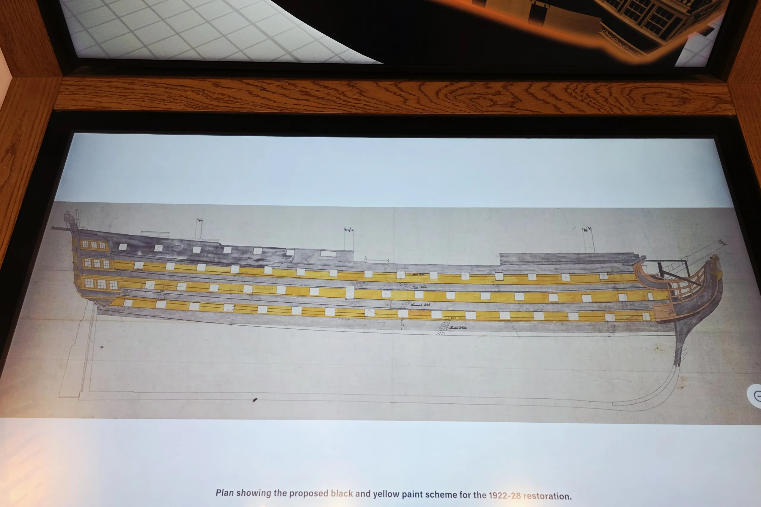
This plan above shows the proposed black-and-yellow colour scheme for the restoration carried out between 1922 and 1928 and can be viewed at the Victory Gallery in Portsmouth.
In 1928, HMS Victory was painted yellow black, but the exact colours she had at Trafalgar were unknown.In 2015, several hundred paint samples were taken from various locations across the ship and in some places they uncovered as many as 72 layers of paint!
This has shown that Victory was painted externally in pale yellow and dark grey at the time of her victory. The National Museum of the Royal Navy has implemented a historically accurate re-painting of Victory allowing visitors to see the ship in her true colours – exactly as she appeared at the Battle of Trafalgar in 1805.
Citation for this text: National Museum of the Royal Navy, Portsmouth
Anchors
Purpose of the various anchors:
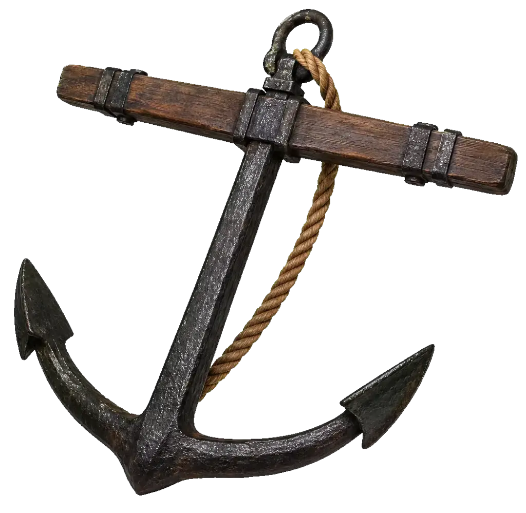
The bower anchors (larboard and starboard) served as main anchors for secure mooring in deep water or strong winds.
The sheet anchor was a reserve for emergencies.
The Kedge Anchor was used for precise maneuvers, while the Stream Anchor was for temporary mooring in shallow waters.
During the repair, restoration, and research work carried out in 1922 at Portsmouth Dockyard, the anchor arrangement was restored to what was probably its configuration in 1805, during the Battle of Trafalgar.
The complement of Trafalgar
| Name | Intended Use | Weight | No. |
|---|---|---|---|
| Best Bower Anchor (Larboard) | Main anchor | 5.542 kg (,54 Tons, 9 cwt, 1 qtr, 14 lbs) | 1 |
| Small Bower Anchor (Starboard) | Main anchor | 5.542 kg (,54 Tons, 9 cwt, 1 qtr, 14 lbs) | 1 |
| Sheet Anchor | Reserve anchor | ~4,409.25 lbs (~2,000 kg) | 2 |
| Kedge Anchor | Maneuvering anchor | ~1.102 to 1.543 lbs (~500 to 700 kg) | 2 |
| Stream Anchor | Temporary mooring | ~3.420 lbs (~1.550 kg) | 1 |
The Anchor Cables of HMS Victory (1805)
Dimensions, Manufacture and Places of Production
Introduction
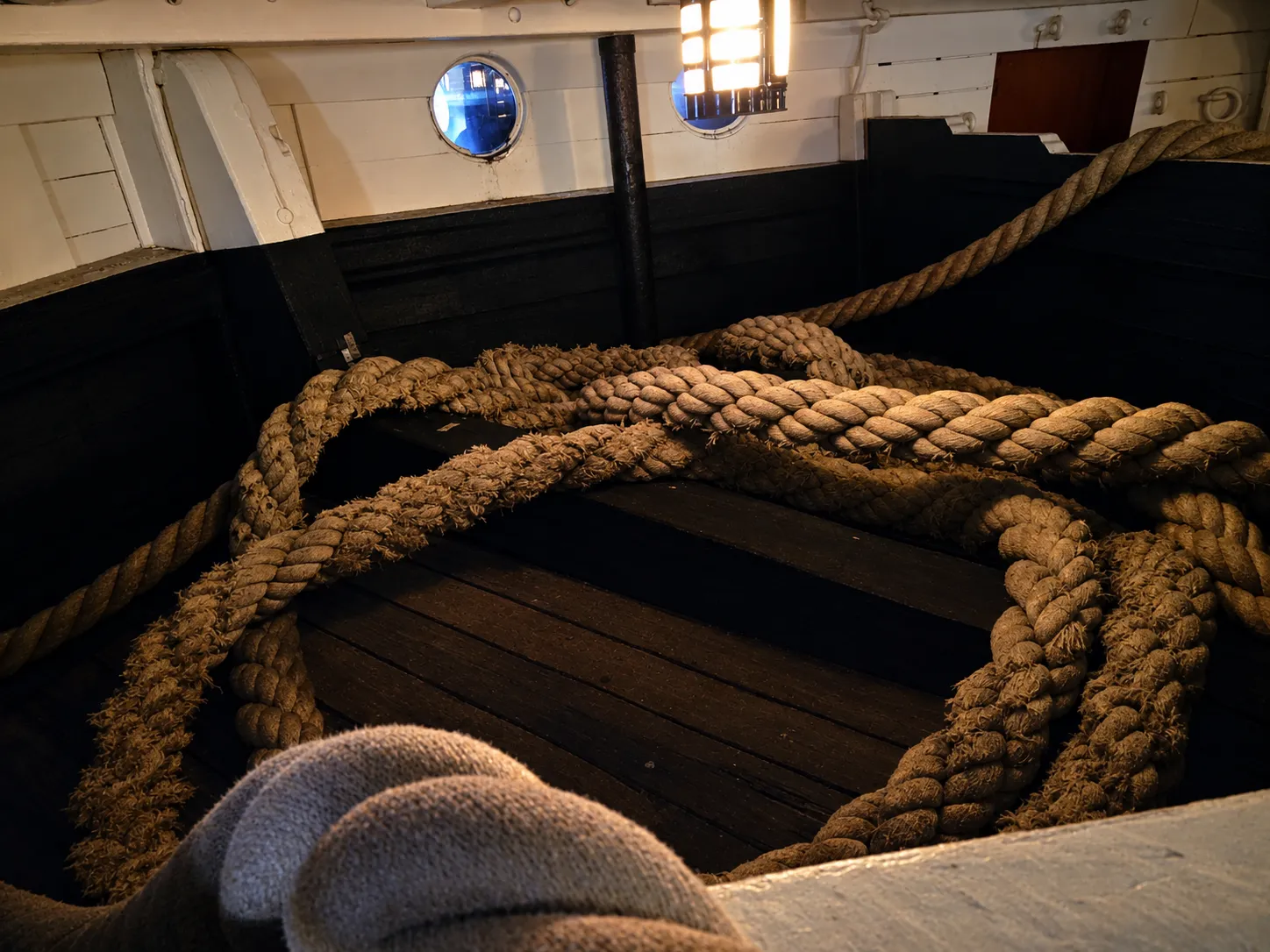
As a First Rate ship carrying 100 guns, HMS Victory was equipped with principal anchors and their associated anchor cables according to Admiralty Establishments. These were among the largest and most technically demanding ropeworks for the Royal Navy.[12]
Construction of Anchor Cables
The anchor cables were manufactured from high-quality hemp as heavy cable-laid ropes, consisting of three substantial strands laid in the opposite direction to the yarns. This construction provided strength, elasticity, and resistance to shock loading. After manufacture, cables were treated with Stockholm tar to prevent moisture damage.
Dimensions of the Principal Anchor Cables
Admiralty Establishments for First Rate ships specified:
| Item | Measurement |
|---|---|
| Circumference | 24 inches |
| Diameter | ~7.64 inches (19.4 cm) |
| Length | 100 fathoms (~183 meters/600 feet) |
| Material | Hemp |
| Construction | Three-strand cable-laid rope |
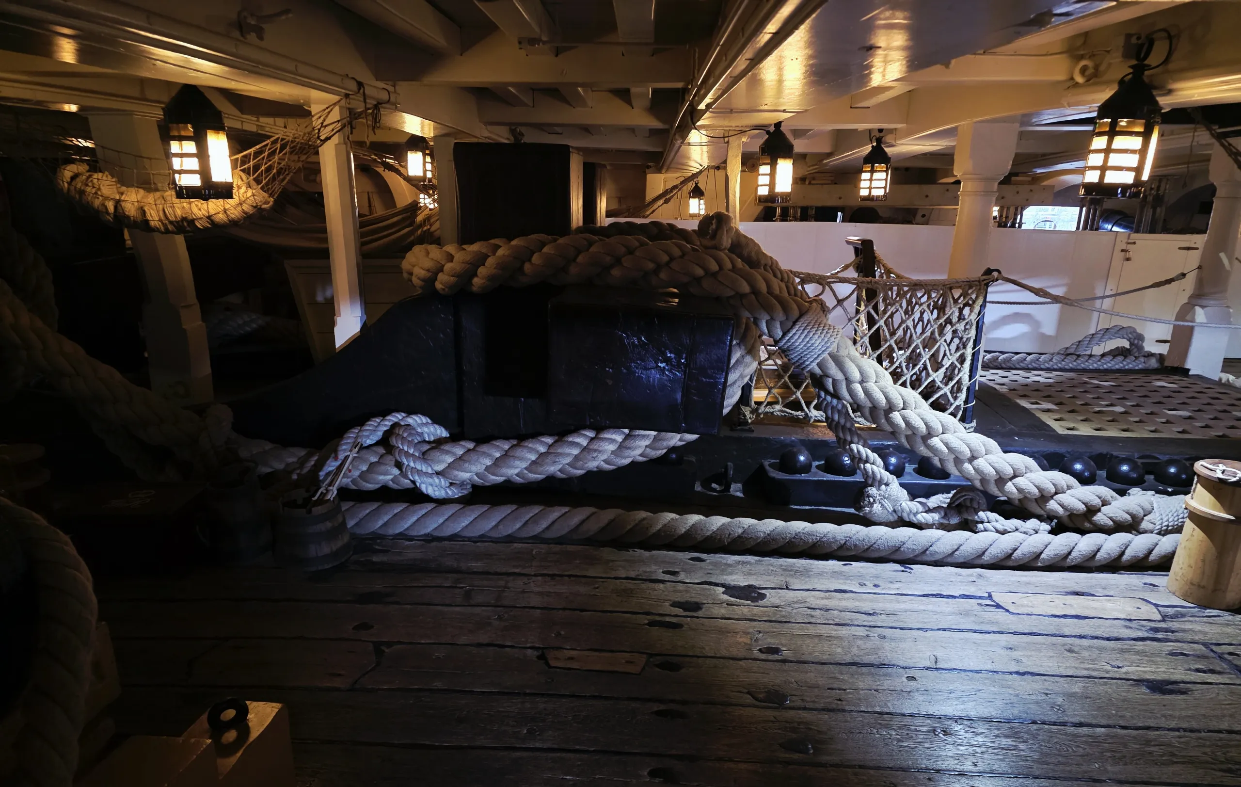
A cable of this size weighed several tons and required specialized equipment and considerable manpower for handling.
Manufacture
Anchor cable manufacture was carried out in Royal Dockyard ropehouses, among Britain’s largest industrial establishments during the Georgian period. The process involved:[13]
- Preparation and combing of imported hemp fibres
- Spinning of yarns
- Formation of strands
- Laying-up of the completed cable
- Tarring and finishing
- Inspection by Navy Board officials
Principal Places of Production
Portsmouth Rope House
The principal source for many ships at Portsmouth was the Royal Dockyard Rope House, a structure over 1,000 feet long enabling manufacture of exceptionally long cables in a single operation. Given Victory’s long association with Portsmouth, many replacement cables were likely manufactured there.
Chatham Ropeyard
The Royal Dockyard at Chatham had a similarly important ropewalk and supplied large quantities of cordage and anchor cables. Production methods were governed by the same Admiralty regulations as at Portsmouth.
Use on Board HMS Victory
HMS Victory carried several classes of anchors: Best Bower, Small Bower, Sheet, and Stream Anchors. The heaviest cables were assigned to the principal bower anchors. When weighing anchor, a continuous messenger cable was used with nippers to attach the anchor cable, allowing it to be drawn aboard progressively as the capstan revolved. The operation required large working parties – over 100 men might be employed at the capstan bars in difficult conditions.
Rigging
The most important dimensions are known from contemporary British Admiralty regulations and reconstructions.[14]
Anchor Cables:
The largest ropes on board were the hemp anchor cables.
| Feature | Value |
|---|---|
| Number of main cables | 6 |
| Length per cable | ~600 ft = 183 m |
| Circumference | 24 inches = 61 cm |
| Diameter | ~7.6-8 inches = 19-20 cm |
| Weight per cable | ~4.5 tons |
| Material | Tarred hemp |
The two main anchors weighed 2-4.5 tons each. Hauling in required up to 144 men at the capstans.
Standing Rigging (Fixed Rigging)
The standing rigging held the masts firmly and consisted of tarred black hemp.
Main Rigging Dimensions:
| Rope | Circumference | Diameter |
|---|---|---|
| Main Stay | 27-30 inches | 22-24 cm |
| Fore Stay | 24-26 inches | 19-21 cm |
| Main Shrouds | 21-24 inches | 17-19 cm |
| Topmast Shrouds | 15-18 inches | 12-14 cm |
| Topgallant Shrouds | 10-12 inches | 8-10 cm |
The Ropery at the former Royal Dockyard in Chatham
The Ropery at the former Royal Dockyard in Chatham was one of the most important sites for the British Navy. Built between 1786 and 1791[15], the building is approximately 346 meters (over 1,100 feet) long – necessary to produce long ship’s ropes in a single piece.
A ship of Victory’s size required about 31 miles (~50 km) of rope for rigging, anchors, and running gear. The ropes for Victory were made in Chatham, and the rope-making workshop still supplies rope for restoration work today. The Ropery is still in operation, considered the last originally preserved naval rope-making workshop in Great Britain.
The company Master Ropemakers continues to produce ropes using traditional methods for historic ships, theatres, film productions, and other specialist applications. Some production still uses Victorian-era machinery. Visitors can tour the Rope Walk and watch the rope makers at work.
The Masts
The Bow Sprit
BOWSPRIT, JIB BOOM & FLYING JIB BOOM
Main Spars and Parts of the Bowsprit
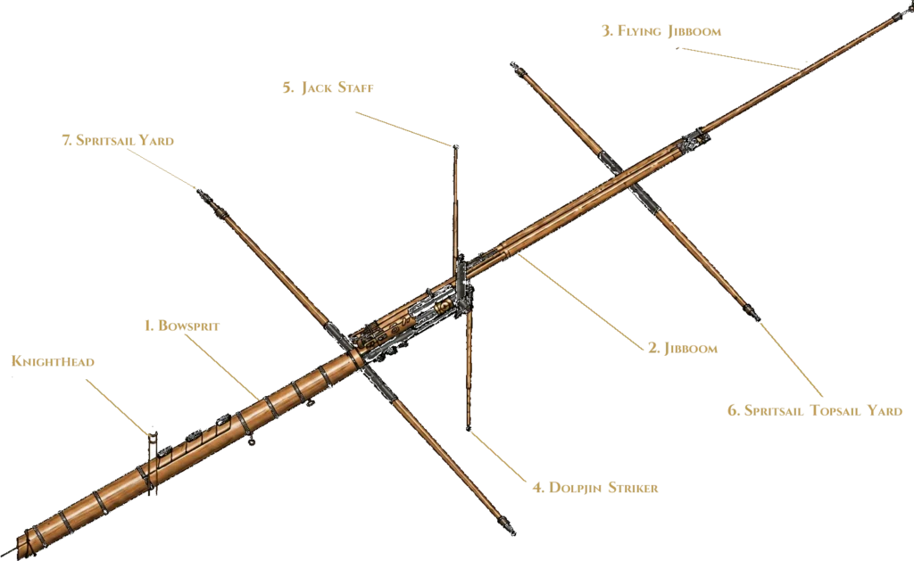
1. Bowsprit
The bowsprit itself (the thick main segment firmly anchored inside the ship’s hull).2. Jibboom
The jibboom segment (the first extension of the bowsprit pointing forward).3. Flying Jibboom
The flying jibboom segment (the outermost, thinner extension furthest forward).4. Dolphin Striker
This spar points vertically downward to tension the stays below.5. Jack Staff (or Sprit Flagpole)
The jack staff. The small flagpole at the very front of the Bowsprit used to hoist the Union Jack in harbor.6. Spritsail Yard
The spritsail yard (the large cross-yard located underneath the bowsprit).7. Spritsail Topsail Yard
The spritsail topsail yard (the smaller cross-yard positioned further forward).8. Larboard and Starboard Bee Blocks
The larboard and starboard Bee Blocks were substantial wooden fittings secured to the sides of the bowsprit. Each contained a sheave through which part of the standing rigging was led.9. Larboard and Starboard Sheaves
The sheaves are the pulleys on the left and right sides of the bowsprit of a historic sailing ship.10. Bowsprit Cap
It is a two-part guide that provides load distribution and serves as an interface for the rigging.11. Boomkin
It is a short, stout wooden spar that projects in pairs (on the larboard and starboard sides) diagonally forward and downward from the bow area.Personal Remark
Although the boomkins are not part of the bowsprit assembly, I have included their dimensions because they are closely associated with the bow structure.| Component | Length Imperial Unit | Length Metric Unit |
|---|---|---|
| Bowsprit from Face of Knight- Heads to end of Flying Jibboom | 112' -7'' | 34,32 m |
| Overall Length of the bowsprit assembly | 132'- 0,5'' | 40,25 m |
| Bowsprit | 64'-5,5'' | 19,65 m |
| Jib Boom | 53' | 16,15 m |
| Flying Jib Boom | 64'-6'' | 19,66 m |
| Dolphin Striker | 18' | 5,49 m |
| Sprit Flagpole | 16'-6'' | 5,03 m |
| Spritsail Yard | 64'-5,5'' | 19,65 m |
| Spritsail Topsail Yard | 43' | 13,11 m |
| Boomkin | 25' | 7,62 m |
The angle of steeve for the HMS Victory’s bowsprit was 30 degrees.
The Fore Mast
Main Spars and Parts of the Fore Mast
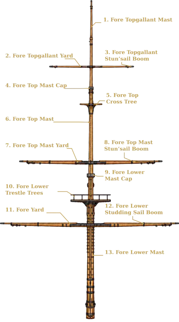
1. Fore Topgallant Mast
The Fore Topgallant Mast segment is the outermost, thinner extension furthest upward.
2. Fore Topgallant Yard
It is a horizontal wooden spar mounted on the third tier of the forward mast (the fore topgallant mast). Its primary purpose is to hold up and spread the top edge (head) of the Fore Topgallant Sail.
3. Fore Topgallant Stun’sail Boom
It is a specialized, temporary wooden spar used to physically extend the width of the ship’s lowest forward sail plan.
4. Fore Top Mast Cap
Serves the exact same mechanical purpose as the lower mast cap, just one tier higher up the rigging assembly.
It is a heavy, iron-reinforced wooden block fitted to the very top of the Fore Topmast. Its primary purpose is to act as a structural collar that links the topmast to the Fore Topgallant Mast above it.
5. Fore Top Cross Tree
Are horizontal timber beams mounted on the second tier of the forward mast (at the head of the Fore Topmast). They run athwartships from larboard to starboard.
6. Fore Top Mast
The Fore Top Mast segment is the first extension of the Fore Mast pointing upward.
7. Fore Top Mast Yard
It is a horizontal wooden spar mounted directly above the Fore Yard. Its primary purpose is to hold up and spread the top edge of the Fore Topsail, which is the second square sail up from the deck on the Fore Mast.
8. Fore Top Mast Stun’sail Boom
It is a specialized, temporary wooden spar used to physically extend the width of the ship’s lowest forward sail plan.
9. Fore Lower Mast Cap
It is a heavy, iron-reinforced wooden block fitted directly onto the very top of the lowest Fore Mast.
Its primary purpose is to act as a structural collar that links the lower mast to the upper mast – the Fore Topmast, holding them rigidly parallel to one another.
10. Fore Lower Trestle Trees
Are two heavy, parallel timber beams running fore-and-aft on either side of the lowest section of the Fore Mast head.
Their primary purpose is to act as the primary load-bearing foundation for the entire upper mast structure and rigging on the Fore Mast. They bear immense downward and lateral forces, transferring all that weight directly into the solid lower mast.
11. Fore Yard
It is a massive, horizontal wooden spar mounted to the Fore Mast that acts as the primary support structure for the ship’s largest forward sails.
12. Fore Lower Studding Sail Boom
It is a specialized, temporary wooden spar used to physically extend the width of the ship’s lowest forward sail plan.
13. Fore Lower Mast
The Fore Lower Mast is the massive primary section of the mast, firmly stepped into the keel structure and extending upward through the decks.
| Component | Length: Imperial Unit | Length: Metric Unit |
|---|---|---|
| Fore Lower Mast above Forecastle Deck | 151' - 10'' | 46.28 m |
| Fore Lower Mast below Forecastle Deck | 38' - 6'' | 11.73 m |
| Fore Lower Mast Total length | 190' - 4'' | 58.0 m |
| Fore Top Mast | 63' - 0'' | 19.20 m |
| Fore Topgallant Mast | 57' - 7'' | 17.55 m |
| Fore Lower Studding Sail Boom | 54' - 0'' | 16.45 m |
| Fore Yard | 89' - 0'' | 27.12m |
| Fore Top Mast Stun'sail Boom | 44' - 6'' | 13.56 m |
| Fore Top Mast Yard | 64'- 6'' | 19.66 m |
| Fore Topgallant Stun'sail Boom | 62' - 3'' | 18.97 m |
| Fore Topgallant Yard | 43' - 0'' | 13.10 m |
| Fore Lower Trestle Trees | 21' - 10'' × 16' - 8'' Dimensions refer to plank sizes before framing. | 6.655 × 5.080 m |
| Fore Top Cross Tree | 6' – 1.5'' × 10 ' - 2.5 '' | 1.86 × 3.11 m |
| Fore Lower Mast Cap | 7' - 1'' × 8'-6.5'' × 1' - 7'' | 2.15 × 2.60 × 0.48 m |
| Fore Top Mast Cap | 3' - 9'' × 1' – 9.5'' × 9.375'' | 1.14 × 0.54 × 0.23 m |
The Main Mast
Main Spars and Parts of the Main Mast
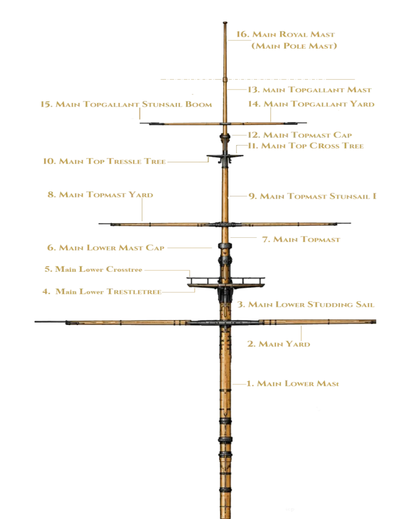
1. Main Lower Mast
The main lower mast is the lower section of the main mast, the tallest and strongest mast of HMS Victory. As the principal structural member of the main mast, it forms the foundation for the mast sections above and supports the standing and running rigging associated with the main mast. Together with the main sail plan, it carries the largest yards and sails of the ship and contributes significantly to her propulsion, stability, and sailing performance.
2. Main Yard
The main yard is the lowest and largest horizontal yard carried by the main mast. It is suspended from the main lower mast and supports the main course, the principal lower square sail of the main mast. As the largest yard in the ship’s rig, it plays a major role in providing propulsive power and is controlled by an extensive system of standing and running rigging.
3. Main Lower Studding Sail Boom
The main lower studding sail boom is a long, retractable spar fitted to each outer end of the main yard. When rigged, it extends beyond the yardarms to support the lower studding sails in favourable weather conditions. By increasing the overall sail area, these booms enable the ship to make greater use of light and following winds.
4. Main Lower Trestle Trees
The main lower trestle trees on HMS Victory are two massive timber beams running parallel along the fore-and-aft line of the ship, positioned at the upper junction of the main lower mast. They form the primary supporting structure for the main top and for the upper mast extension.
5. Main Lower Crosstrees
The main lower crosstrees are heavy transverse timber beams mounted across the main lower trestle trees at the head of the main lower mast. Together with the trestle trees, they form a rigid supporting framework for the main top while providing lateral support and accurate positioning for the mast section above.
6. Main Lower Mast Cap
The main lower mast cap is a heavy, solid timber fitting mounted at the upper end of the main lower mast. It serves as the primary structural coupling and securely joins the lower mast with the mast section above, the main topmast. Acting as the interface between the lower mast and its extension, the cap is firmly seated on the square head of the main lower mast. In addition to the square mortise for the lower mast, the cap incorporates a second, circular opening, offset slightly forward, through which the heel of the main topmast passes. Once stepped through this opening, the topmast is securely seated and restrained in position.
7. Main Topmast
The main topmast is the second, or middle, section of the main mast, the tallest mast of Victory. Stepped through the main lower mast cap and securely supported by the main lower mast, it extends the mast upward to carry the upper main rigging and the sails set above the lower mast. Together with the main lower mast, it forms an integral part of the ship’s main mast assembly.
8. Main Topmast Yard
The main topmast yard is the middle horizontal yard carried by the main mast. It is positioned directly above the main yard, at the level of the main topmast. Its primary function is to support, spread, and control the main topsail. The sail is permanently attached and secured to this yard.
9. Main Topmast Studding Sail Boom
The main topmast studding sail boom is a retractable spar fitted to each outer end of the main topmast yard. It extends the width of the yard when the topmast studding sails are set in favourable weather. These booms increase the effective sail area and improve the ship’s performance in light winds.
10. Main Top Trestle Trees
The main top trestle trees are two parallel timber beams positioned at the upper end of the main topmast. They form the supporting framework for the uppermost mast extension and for the associated topmast rigging supports.
11. Main Top Crosstrees
The main top crosstrees are transverse timber beams mounted across the main top trestle trees at the head of the main topmast. Together with the trestle trees, they provide the structural support required for the main topgallant mast while maintaining its correct alignment and stability.
12. Main Topmast Cap
The main topmast cap is a heavy, solid timber fitting located at the head of the main topmast. It serves as the structural coupling that securely connects the main topmast with the mast section above, the main topgallant mast. Whereas the main lower mast cap forms the connection between the lower mast and the topmast, the main topmast cap is positioned one stage higher in the mast assembly. Acting as the seating and support for the uppermost mast extension, it is firmly fitted over the square head of the main topmast. In addition to its square mortise for the topmast, the cap incorporates a second, circular opening offset slightly forward, through which the heel of the main topgallant mast passes. Once stepped through this opening, the topgallant mast is securely seated and restrained in position.
13. Main Topgallant Mast
The main topgallant mast is the third section of the main mast. Stepped above the main topmast, it continues the vertical mast assembly and provides support for the upper standing and running rigging of the main mast. It carries the main topgallant yard, from which the main topgallant sail is set.
14. Main Topgallant Yard
The main topgallant yard is the upper horizontal yard carried by the main mast. It is positioned directly above the main topmast yard on the main topgallant mast. Its primary function is to support and spread the main topgallant sail. This sail makes effective use of the stronger winds at higher elevations, improving the ship’s speed, particularly in moderate and light airs.
15. Main Topgallant Studding Sail Boom
The main topgallant studding sail boom is a light, retractable spar mounted at each end of the main topgallant yard. It supports the topgallant studding sails when additional sail area is required in favourable weather conditions. By extending the sail plan beyond the yardarms, these booms increase the vessel’s driving power in light winds.
16. Main Royal Mast (Main Pole Mast)
The main royal mast, also known as the main pole mast, is the uppermost and final section of the main mast. Stepped above the main topgallant mast, it completes the vertical mast assembly and supports the highest standing rigging together with the signal and rigging fittings carried at the masthead. Although considerably lighter than the mast sections below, it forms the final extension of the ship’s principal mast and contributes to the complete height and rig of the main mast.
| Component | Length - Imperial Unit | Length - Metric Unit |
|---|---|---|
| Main Lqwer Mast above Quater Deck | 77' - 6'' | 23,62 m |
| MainLqwer Mast below Quater Deck | 41' - 6'' | 12,65 m |
| Main Lower Mast Total length | 119' - 0'' | 36,27 m |
| Mai top Mast | 70' - 0'' | 21,346 m |
| Main Topgallant Mast | 58' - 6'' | 17,83 m |
| Main lower studding Sail Boom | 61' - 0'' | 18,59 m |
| Main Yard | 102' - 4'' | 31,19 m |
| Main Topmast Stun'sail Boom | 51' - 2'' | 15,60 m |
| Main Topmast Yard | 73 '- 0'' | 22,25 M |
| Main Sopgallant stun'sail Boom | 36' - 6'' | 11,13 M |
| Main Topgallant Yard | 48' - 6'' | 14,78 m |
| Main Lower Trestle trees | 23'-6'' x 17'-8'' sizes are Planksizes without frameing | 7,16 x 5,38 m |
| Main Top Cross Tree | 11'-3'' x 6'-9'' | 3,43 x 2,06 m |
| Main Lower Mast Cap | 7' - 2'' x 5'' - 7,5'' x 1' - 7,5'' | 2,18 x1,71 x 0,5 m |
| Main Top Mast Cap | 4'-1''1 x 2' - 0'' x 11'' | 1,24 x 0,61 x 028 m |
The Mizzen Mast
Main Spars and Parts of the Mizzen Mast
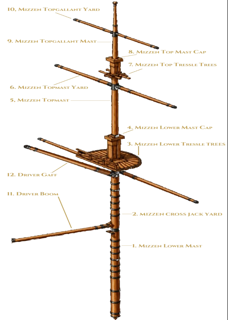
1. Mizzen Lower Mast
The mizzen lower mast is the lower section of the mizzen mast, the aftermost mast of HMS Victory. As the principal structural member of the mizzen mast, it forms the foundation for the mast sections above and supports the standing and running rigging associated with the mizzen mast. In conjunction with the mizzen sail plan, it contributes significantly to the ship’s balance, steering characteristics, and manoeuvrability.
2. Mizzen Cross Jack Yard
The mizzen crossjack yard is the lowest horizontal yard carried by the mizzen mast of HMS Victory. Its distinctive feature is that, unlike the other lower yards, it does not carry a sail and serves a purely structural purpose. Its primary function is to spread the lower mizzen rigging and to provide attachment and fair leads for the braces, clewlines, and other running rigging associated with the yards above. By supporting this rigging, the crossjack yard contributes to the efficient handling and control of the upper mizzen sails.
3. Mizzen Lower Tressle Trees
The mizzen lower trestle trees on HMS Victory are two massive timber beams running parallel along the fore-and-aft line of the ship, positioned at the upper junction of the lowest section of the mizzen mast. They form the primary supporting structure for the platform above (the mizzen top) and for the upper mast extension.
4. Mizzen Lower Mast Cap
The mizzen lower mast cap is a heavy, solid timber fitting mounted at the upper end of the mizzen lower mast. It serves as the primary structural coupling, securely joining the lower mast with the mast section above, the mizzen topmast. Acting as the interface between the lower mast and its extension, the cap is firmly seated on the square head of the mizzen lower mast. In addition to the square mortise for the lower mast, the cap incorporates a second, circular opening, offset slightly forward, through which the heel of the mizzen topmast passes. Once stepped through this opening, the topmast is securely seated and restrained in position.
5. Mizzen Top Mast
The mizzen topmast is the second, or middle, section of the mizzen mast, the aftermost mast of HMS Victory. Stepped through the mizzen lower mast cap and securely supported by the mizzen lower mast, it extends the mast upward to carry the upper mizzen rigging and the sails set above the lower mast. Together with the mizzen lower mast, it forms an integral part of the ship’s mizzen mast assembly.
6. Mizzen Topmast Yard
The mizzen topmast yard is the middle horizontal yard on the mizzenmast of HMS Victory. It is positioned directly above the crossjack yard, at the level of the mizzen topmast.
Its primary function is to support, spread, and control the mizzen topsail. The sail is permanently attached and secured to this yard.
7. Mizzen Top Tressle Trees
The mizzen top trestletrees on HMS Victory are two parallel timber beams positioned at the upper end of the mizzen topmast. They form the supporting framework for the uppermost mast extension and for the associated topmast rigging supports.
8. Mizzen Topmast Cap
The mizzen topmast cap on HMS Victory is a heavy, solid timber fitting located at the head of the mizzen topmast. It serves as the structural coupling that securely connects the mizzen topmast with the mast section above, the mizzen topgallant mast.
Whereas the mizzen lower mast cap forms the connection between the lower mast and the topmast, the mizzen topmast cap is positioned one stage higher in the mast assembly. Acting as the seating and support for the uppermost mast extension, it is firmly fitted over the square head of the mizzen topmast. In addition to its square mortise for the topmast, the cap incorporates a second, circular opening offset slightly forward, through which the heel of the mizzen topgallant mast passes. Once stepped through this opening, the topgallant mast is securely seated and restrained in position.
9. Mizzen Topgallant Mast
The mizzen topgallant mast is the uppermost and final section of the mizzen mast, the aftermost mast of HMS Victory. Stepped above the mizzen topmast, it completes the vertical mast assembly and provides support for the highest standing and running rigging of the mizzen mast. It carries the mizzen topgallant yard, from which the mizzen topgallant sail is set.
10. Mizzen Topgallant Yard
The mizzen topgallant yard is the uppermost yard carried by the mizzen mast of HMS Victory. It is positioned in the highest section of the mast, directly on the mizzen topgallant mast.
Its primary function is to support and spread the mizzen topgallant sail. This sail captures the wind from the higher air currents, which can increase the vessel’s speed, particularly in light winds.
11. Driver Boom
The driver boom is the long, horizontal wooden spar attached to the foot of the mizzenmast and extending far beyond the stern (aft end) of HMS Victory.
It forms the lower counterpart to the driver gaff. Together, these two spars stretch and support the large, trapezoidal stern sail.
Its primary function is to spread and support the foot (the lower edge) of the driver or spanker sail. Without this boom, the sail would collapse inward under the pressure of the wind.
12. Driver Gaff
The driver gaff is a wooden spar set at an upward angle, which is attached in a movable manner to the mizzenmast of HMS Victory.
It forms the upper counterpart to the driver boom. Together, these two spars stretch and support the large, trapezoidal stern sail.
Its primary function is to spread and support the upper edge of the sail (the driver or spanker).
The gaff is controlled by two rope systems. The gaff halyard raises the gaff along the mast. The topping lift (dirk) supports the outer end of the gaff (the gaff peak), maintaining it at the correct height and taking up its weight.
| Component | Length - British Imperial Units | Length - Metric Units |
|---|---|---|
| Mizzen Lower Mast_ View - Poop Deck Line to the Bottom Mastend | 46' - 0'' | 14,021 m |
| Mizzen Lower Mast_ View - Poop Deck Line to the Top Mastend | 55' - 4'' | 16,866 m |
| Poop Deck Line to Top of Royal Mast | 127' – 2.75'' | 38,780 m |
| Mizzen Lower Mast | 102' - 0'' | 31,090 m |
| Mizzen Topmast | 51' - 0'' | 15,545 m |
| Mizzen Topgallant Mast | 26' - 0'' | 7,925 m |
| Mizzen Royal Mast | 13' - 0'' | 3,962 m |
| Cross Jack Yard | 66' - 0'' | 20,117 m |
| Mizzen Topmast Yard | 46' - 0'' | 14,021 m |
| Mizzen Topgallant Yard | 32' - 9'' | 9,982 m |
| Driver Boom | 74' - 11'' | 22,835 m |
| Driver Gadd | 61' – 1.5'' | 18,631 m |
| Mizzen Lower Tressle Trees | 16' – 6'' x 12' - 6'' | 5,029 × 3,810 m |
| Mizzen Top Tressle Trees | 8' – 6'' x 5' - 1'' | 2,591 × 1,549 m |
| Mizzen Lower Mast Cap | 5' – 0'' x 2' – 6'' x 1' - 1'' | 1,524 × 0,762 × 0,330 m |
| Mizzen Topmast Cap | 2' – 1.5'' x 1' – 5'' x 8'' | 0,648 × 0,432 × 0,203 m |
Historical References
- Original ship plans, Chatham Dockyard, 1759–1765: Technical drawings and specifications for HMS Victory. [1a] [1b]
- Royal Navy trials and records: Copper sheathing experiments (1761–1783) and adoption across the fleet. Includes the HMS Alarm trial of 1761 and standardisation by 1783. [2]
- Portsmouth Dockyard refit records: HMS Victory copper sheathing installation, 1778–1780. Details include approximately 3,500 copper plates measuring 4 ft × 14 in, fastened with copper nails. [3]
- Admiralty technical reports: Electrochemical corrosion issues between copper plates and iron bolts, and the solution using copper fastenings. Documents original copper bolts up to three metres long found during conservation. [4]
- Admiralty records: Armament configuration of HMS Victory at the Battle of Trafalgar, 21 October 1805. [5]
- Royal Gun Foundry Woolwich Arsenal records: Manufacturing details of 32-pounders, 24-pounders, and 12-pounders for HMS Victory. [6]
- Carron Company, Falkirk, Scotland: Production records of 68-pounder carronades supplied to the Royal Navy. [7]
- Naval warfare records: Documented effectiveness of carronades at close range, under 500 yards, during late 18th-century engagements. [8]
- Technical specifications: Design advantages of carronades, including faster reloading, stability at sea, and reduced crew requirements. [9]
- National Museum of the Royal Navy restoration records, 1800–1803: Documentation of repainting during the Great Repair, including adoption of the Nelson Chequer pattern. [10]
- Admiralty anchor specifications, late 18th century: Technical details of anchors aboard HMS Victory, including dimensions and weights. [11]
- Admiralty Establishments for First Rate Ships: Anchor cable specifications, including a 24-inch circumference, approximately 183-metre length, and standardisation requirements. [12]
- Royal Dockyard records: Rope manufacturing processes at Portsmouth and Chatham dockyards, including quality control and inspection procedures. [13]
- British Admiralty regulations, late 18th century: Contemporary specifications for rigging dimensions and materials aboard ships of the line. [14]
- Historic Dockyard Chatham records: Construction between 1786 and 1791 and continuous operation of the Ropery, including its role in supplying rope for HMS Victory. [15]